The supercharger is currently off the motor, and I plan to get the Haltech up and running and work through setup on the majority of new systems with the car naturally aspirated and then reintroduce boost.
With the change to a universal ECU, it didn’t make sense to retain the GM throttle pedal and TB and have to work out the calibration and quirks of those – far easier to convert to a well known TPS and DBW TB. So I now have a TPS on the Tilton throttle pedal and made an adapter to fit a Bosch throttle body from a Porsche 997 application to the LFX intake manifold:
Work on the car has continued. Since covid hit we’ve been busier than ever at Goodwin Racing (a good problem to have) and that’s meant that with the little spare time I have it often comes down to whether I want to use that time to build the car, or write about it… and I’m determined to finish this thing up and get back to the track, so it’s been head down and getting after it for the past year. There’s a lot of updates to make, so to keep things digestible I’ll break it up into smaller chunks and do those updates over a little time here.
First, the fuel system. The plan is to get rid of the factory GM ECU since that’s proved to be a limitation in tuning the supercharger. But most aftermarket ECUs can’t run direct injection. And the DI system has been a source of headaches in trying to get enough fuel for the supercharger anyways… so I made the decision to go the hard route and completely eliminate the DI by converting the engine to a more traditional port injection format.
Thanks to a discovery made by one of the other LFX swapped guys over on Miataturbo.net, we figured out there was one piece to this puzzle already available from GM; a lower intake manifold that already had injector ports in it. I got my hands on one of these, but that’s where the easy stuff ended. Fuel rails are needed.
First mock-up of that manifold on the LFX, and in the picture I’m already starting to plan out rail placement:
With this new setup, I’ll be running 6 x Injector Dynamics ID 1300x:
Had a little back and forth with the guys at ID to sort out the exact combination of top and bottom o-ring sizes plus a small spacer to get its placement in the manifold just right.
Due to the port placement, the rail has to be a few inches away from the injector, and at a different angle. This means the rail needs “fingers” that extend to the injector. The fingers need to be precision sized at both ends, bent at an angle, rigid, and also need to seal to the rail. This lead me down a whole spiral of researching the mechanics of o-rings and seals so I could design this to seal properly, and then figuring out how to make the necessary multi-piece design.
Some progress shots:
Pressure testing:
Polished and anodized:
And that’s a finished set of one-off fuel rails test fit on the spare motor:
This can now be fed by a normal fuel supply system at normal fuel pressure. FPR will be mounted on the back of the motor near the rail and then split to both rails. And this will now be a return system with return line exiting the rails and going back to the tank. I just need to make a couple lines and the fuel injector wiring sub harness and then this will be installed on the main engine in the car.
Oh, and the DI ports in the head were drilled/tapped and plugged, and the port on the back of the motor for the high pressure mechanical fuel pump was capped:
Rear brakes needed some changes to accommodate the 5×114 change as well. First, new hat was obviously needed with the new lug pattern. V8Roadster’s front hats for their NC floating BBKs had the bolt pattern I needed, and after much comparing of measurements, the other dimensions were close enough that they’d work on the car with some adjustments to surrounding bits. Bonus is these are designed to use the same StopTech 8mm floating hardware as the new front brakes, so same hardware all around.
The 5 lug hats have a slightly different offset than the previous NA/NB sport rotor hats, so I made a correction to the brackets to account for that:
The 5 lug hats are also slightly larger in total diameter than 4×100 hats, which caused an interference with the caliper. So rotor friction ring ID and OD were increased slightly to get the clearance needed. Then I fired up the lathe for my first real project with that machine and made small radial spacers to move the caliper for the larger diameter. The finish on them could be better, learning as I go, but paired with longer bolts they’ll work perfectly:
Finally, the 5 lug hats have a center register hole for an NC hub, but my rear 5 lug Miatahubs were made with a center to match NA/NB specs. So project #2 with the lathe was a set of hubcentric adapter rings for the rear rotors.
Started with this:
Progress shot, this is after all the forming operations, just starting to part off the individual pieces:
And individual rings finished and back from anodizing. Two for the car, one for the spares box:
Centering ring mounted up with the new rotor on the 5 lug Miatahub, carnage in the background…
And as I mentioned previously, the change to 5×114 had a domino effect that resulted in my revising everything in the brake system. The new front setup borrows the 309x32mm rotors from StopTech’s NC BBK, and uses the StopTech C43 caliper in nickel finish with SS noses and piston sizes chosen for this car’s brake setup and targets. But the critical caliper bracket to fit these parts to an NA/NB doesn’t exist, and that’s precisely why I invested in a vertical mill this year. I machined radial brackets in house, and now have Hyper’s new front brake package completed.
Started with this:
Learned a ton these past couple months figuring out the mill. Making these brackets took some creative setups and getting familiar with the rotary table. Progress:
Final brackets finished, anodized, and studs installed:
Full package for one side:
Test fit. Naturally, miles of room inside this big 18×11:
Tubbing the chassis is finished! We now have full unhindered bump travel in the suspension front and rear, with turning in the front. It’s required some substantial cutting and reshaping of the front and rear tub, side exhaust, side skirts, and suspension geometry changes. I still have the body work ahead of me, but pretty darn happy to have reached this point. Here is the suspension at full compression:
Sitrep on the chassis clearancing for the big wheels:
I have the front right corner all welded up. Rebuilding the wheel well involved 13 different hand made sections, including several internal support pieces to ensure load transfer isn’t compromised.
I was going to move to the left side and do the same, but on the driver’s side there’s a complication: the tire hits the clutch master. Significantly. Yeahhh, you read that right. So the clutch master can’t be on the engine side of the firewall. The need to re-do the clutch pedal snowballed a bit, and I’m doing a full pedal box now, so the booster and 929 MC will be deleted.
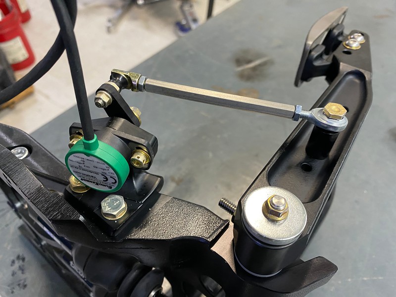
A pedal box isn’t a small bit of work, so that’s what I’ve been working on for the past week and a half. It really changes the ergonomics as well. I had to re-build the throttle pedal mount to raise that pedal 2″ so it is in-line with the new pedals as my heel sits on the false floor now.
Here’s an in-progress shot as its sits right now. Everything is mounted and the false floor is made. I have some grippy stuff on the way for the floor. Next up is to measure and figure out each line length, fittings, etc. and get all the brake and clutch lines in the works.
A non-boosted brake system needs entirely different piston sizes at both the masters and the calipers than a boosted system. So I’ve been back and forth with the StopTech guys and we’re swapping all the calipers out for new ones with different piston sizes to make everything right for the new configuration. Conveniently, I was already going to have to basically build a whole new brake system at each corner anyways thanks to the 5 lug change… so it’s the right time to do this.
I chose the 850 pedal box because it has a throttle pedal with DBW compatibility. When I move to a standalone ECU (more on that later), if there are any issues with the GM pedal I could switch to the Tilton pedal and DBW sensor which is easy to configure in a standalone.
The necessity to dramatically change the brakes really stemmed from two things: A) The 5 lug conversion meant the rotor hats had to change. That of course had a domino effect; rotor hat diameter increased slightly, causing caliper interference, etc. etc. and ultimately it led to revisiting every component in the brake system on all four corners… B) When I discovered the larger tires interfered with the clutch master cylinder, I had to figure out a new clutch pedal/MC at a minimum, and that lead things down the path of deciding a pedal box was the way to go since it would solve my clutch pedal needs, and eliminating the brake MCs in the engine bay would free up some much needed space as well.
The past month has seen a lot of sidetracks. I’ve had the plan for this big wheel project largely figured out, but left a few details open ended until I got in there and really had a chance to look at things from every angle. Now that I’m there and gone over things a dozen times I’ve decide to change the configuration a bit from what I was originally planning. That means a few more custom parts. One or two things I’m not ready to take the cover off yet until I’m sure they’ll all come together the way I have envisioned, but most importantly several things require machining that up until now I’d have to send out for. Every time I have to send out for machining there’s a big stop and wait in the project, and finally I decided I need to have some machining capability in-house.
So off I went on a giant sidetrack shopping for a vertical mill and metal lathe. Didn’t have the budget for a new mill, so scoured Craigslist until I found a nice ACRA unit with everything I wanted. Then I had to get it from LA to San Diego, then rent a forklift and get it in the building, then get the shop area wired up for 3 phase power, then get tooling etc. for it. Just finishing that up, with the last part of that project being a new DRO system on the way and then I should be ready to start cutting with it. I also have an order in for a Precision Matthews lathe, which should be coming in another couple weeks. There will undoubtedly still be some machining jobs I need to send out for, but with this equipment I should be able to tackle probably 75% of the machining work that I come across needing to do. So while it’s caused a delay up front I’m excited to have cut down on delays in the future.
A few more pieces of the puzzle arrived during all that.
Aluminum driveshaft to transfer things between the Jerico yoke and Getrag diff:
New rear friction rings which will go on new 5 lug rotor hats:
Rode the struggle bus today. Those of you who are machinists will be saying “yeah duh!”
Transmission adapter plate came back fresh from anodizing today. Unwrapped it like it was Christmas to find… instead of gold, it was brown. The anodizer had told me that Type III hard anodizing comes out a shade or two darker than normal Type II… but assured me it would just be “darker gold”. Not much that can be done now, it’s a precision part so I’m not going to have it stripped/blasted and redone just for a color change, and I know, I know, you’ll never see it once it’s in the car, but I was stoked to get this part I have months of time into nicely finished in a sexy color, so the “wood brown” as I’m affectionately calling it now was a bummer.
So OK, moving on. Since the plate is back I’ll take a break tonight from working on the chassis and do some final fit checks with the transmission. Ah, but that’s no good either because Type III anodizing adds up to 0.004″ thickness (which the anodizer didn’t feel like mentioning when I specifically asked if there were any factors I should consider for choosing between Type II and III) and when we’re talking about a hole with two walls that’s almost a hundredth of an inch. So none of the alignment dowels fit any more. Doh!
I’ve got some reamers on the way to correct the holes so I’ll have it sorted out soon enough. C’est la vie.
Picture above also shows the flywheel mounted up with the new clutch; a Tilton 7.25 cerametallic twin plate.
Here’s the new clutch and flywheel for the 4 speed dog box compared to the old Spec combo for the GM tranmission:
Left side of car is finished cutting. Before I start welding stuff in I have to cut the other side to match.
Still early days on this project but getting pretty excited for how it’s going to turn out. Approaching this from the standpoint of picking the wheel and tire I want to be on, placing the chassis where I want it relative to that, and just making everything else work around that. It’s the right way to do it… but certainly intrusive. The list of items and areas that have to be cut, modified, relocated, reinforced, etc. has grown substantially from what I had in mind going into it.
Detour from cutting up the chassis for a moment. After months of measuring, drawing, triple checking and revising drawings… parts are materializing to move the transmission project forward.
Got this picture from CNC of the adapter plate being born:
Less than 24 hours later I had it test fit to the motor, a couple final adjustments made, and now it’s off to anodizing:
With the adapter here I was able to mock up the bellhousing to the motor for the first time and do some trimming on that so that it now mounts up:
And apparently Monday all the stars and planets were aligned because on that same day the custom flywheel arrived. This baby is CNCd from a single piece of chromoly, designed for a 7.25″ twin plate clutch, with a welded ring gear and integral pilot bearing (So happy to have a pilot bearing after the MV5/7 design that doesn’t have one). It’s almost 10 lbs lighter than the ‘lightweight’ aluminum flywheel from Spec, and almost 20 lbs lighter than the factory flywheel.